

 English
 中文简体
中文简体 Español
 русский
NBC-315S/NBC-350S 380V 350A IGBT Inverter Portable welder 2T/4T MIG/MAG/MMA(GMAW/SMAW)
Cat:Gas shielded welding machine
1、The welding machine is small and can be connected to a wire feeder. ...
See DetailsA submerged arc welding (SAW) machine is an industrial welding system that produces high-quality, deep-penetration welds by running an electric arc beneath a blanket of granular flux. It consistently delivers deposition rates of 15 to 45 kg/hour — four to ten times faster than manual MIG or stick welding — making it the go-to choice for heavy fabrication in shipbuilding, pressure vessel manufacturing, structural steel, and pipeline construction.
If you're evaluating SAW machines for an industrial application, this guide covers how they work, the key machine types, what specifications actually matter for your use case, typical operating parameters, and how to avoid the most common setup mistakes.
Content
Unlike MIG or TIG welding, the arc in SAW is completely hidden. A continuous bare wire electrode feeds into the weld zone, while granular flux is deposited ahead of and around the arc from a hopper. The flux serves three critical functions: it shields the molten pool from atmospheric contamination, it stabilizes the arc electrically, and it contributes alloying elements to the weld metal.
Because the arc is submerged, there is virtually no spatter, no UV radiation exposure, and extremely low fume generation compared to open-arc processes. The unconsumed flux is recovered by a vacuum system and can often be recycled, reducing operating costs significantly.
The core components of a SAW machine system are:
Submerged arc welding machines are configured differently depending on the geometry and scale of the workpiece. Choosing the right machine type before evaluating specific models is essential.
The welding head and flux hopper are mounted on a motorized tractor that rides on rails or directly on the workpiece. This is the most versatile configuration, used for long straight seams on flat plate, structural members, and large weldments. Travel speeds typically range from 25 to 200 cm/min, adjustable depending on material thickness and heat input requirements.
A fixed or rotating column supports an extendable horizontal boom that carries the welding head. These systems are used for welding large cylindrical vessels, tanks, and heavy structural components. The boom reach typically spans 2 to 6 meters, and the column can be floor-mounted or travel on floor rails for additional flexibility.
The workpiece (typically a pipe or pressure vessel) is rotated on a turning roll positioner while the welding head remains stationary. This is the standard setup for circumferential seam welding of pipes and cylindrical pressure vessels. It produces highly consistent girth welds with minimal setup time between passes.
A bridge-style frame straddles the workpiece, with the welding head traveling along the bridge. Gantry systems are used for extremely wide flat plates and ship hull sections, where rail-based tractors are impractical. Some shipyard gantries span over 20 meters in width.
Two or more wire electrodes feed into the same weld pool or in tandem. Twin-wire and tandem SAW configurations can push deposition rates above 60 kg/hour while maintaining weld quality, making them essential in high-volume pipe mill and shipbuilding operations.
When comparing SAW machines, the following specifications have the most direct impact on performance and suitability for your application:
| Specification | Typical Range | Why It Matters |
|---|---|---|
| Rated Welding Current | 600A – 1500A | Determines maximum material thickness and wire diameter supported |
| Duty Cycle | 80% – 100% at rated current | SAW is a continuous process; anything below 100% causes costly downtime |
| Wire Feed Speed Range | 0.5 – 5 m/min | Controls deposition rate and current; wider range = more process flexibility |
| Wire Diameter Capability | 2.0 – 6.0 mm | Larger wire = higher deposition; smaller wire = finer control on thinner material |
| Travel Speed Range | 15 – 250 cm/min | Affects heat input and bead geometry; variable speed is essential for procedure qualification |
| Power Source Type | DC, AC, or DC+AC | DC = stable arc, preferred for single wire; AC reduces arc blow in multi-wire setups |
| Flux Hopper Capacity | 10 – 50 kg | Larger capacity = fewer flux refills on long continuous seams |
Duty cycle is the most overlooked specification. Many lower-cost machines are rated at 1000A but only at 60% duty cycle, meaning they require rest periods during continuous operation. For production welding, always insist on a machine rated at 100% duty cycle at its working current range.
Setting the right parameters is critical to achieving the required weld penetration, bead profile, and mechanical properties. The table below gives practical starting-point parameters for carbon steel using a single DC electrode positive (DCEP) configuration:
| Plate Thickness (mm) | Wire Diameter (mm) | Current (A) | Voltage (V) | Travel Speed (cm/min) |
|---|---|---|---|---|
| 6 – 10 | 2.4 – 3.2 | 400 – 600 | 28 – 32 | 60 – 90 |
| 12 – 20 | 3.2 – 4.0 | 600 – 800 | 30 – 36 | 40 – 70 |
| 20 – 40 | 4.0 – 5.0 | 800 – 1100 | 34 – 40 | 25 – 50 |
| 40+ | 5.0 – 6.0 | 1100 – 1500 | 36 – 44 | 15 – 35 |
These are starting points only. Actual qualified welding procedures (WPS/PQR) must be developed and tested per applicable codes such as AWS D1.1, ASME Section IX, or EN ISO 15614-1, depending on your industry and jurisdiction.
The flux-wire combination in SAW is equivalent to the electrode in stick welding — it determines the mechanical properties, crack resistance, and impact toughness of the finished weld. The two are not interchangeable at will; they must be matched as a system.
SAW wires are classified under AWS A5.17 (carbon steel), AWS A5.23 (low alloy steel), and AWS A5.9 (stainless steel), among others. For carbon steel structural work, EM12K wire paired with an agglomerated basic flux is a common industry standard combination that reliably achieves Charpy impact values above 47J at −20°C — a common acceptance criterion for offshore and pressure vessel work.
Always specify wire and flux together when ordering consumables, and verify the combination has been tested and certified per the applicable standard if code compliance is required.
SAW is not always the right tool, even for heavy fabrication. Understanding where it outperforms alternatives — and where it doesn't — prevents expensive equipment investments that don't match the actual workflow.
| Process | Deposition Rate | Positional Welding | Min. Practical Thickness | Best For |
|---|---|---|---|---|
| SAW | 15 – 45+ kg/hr | Flat / horizontal only | ~5 mm | Long flat seams, thick plate, pipes |
| FCAW (Flux-Cored) | 5 – 15 kg/hr | All positions | 1.5 mm | Structural field welding, complex geometry |
| GMAW (MIG) | 3 – 8 kg/hr | All positions | 0.5 mm | General fabrication, thin to medium material |
| Electroslag Welding | 15 – 30 kg/hr | Vertical only | ~25 mm | Very thick vertical joints in single pass |
SAW's primary limitation is that it is restricted to flat (1G) and horizontal fillet (2F) positions. The molten flux pool is too fluid to hold in overhead or vertical positions. Any application requiring out-of-position welding needs a complementary process or workpiece manipulation equipment to bring joints into the flat position.
Even experienced welding engineers encounter avoidable problems when commissioning or running SAW equipment. These are the most frequent issues in practice:
CTWD in SAW is typically 25 to 38 mm for standard single-wire configurations. Too short increases burn-back risk and flux entrapment; too long causes excessive resistive preheating of the wire, reducing penetration and destabilizing the arc. Check and set CTWD at the start of every production run.
Moisture in flux is one of the leading causes of porosity and hydrogen-induced cracking in SAW. Agglomerated fluxes must be stored below 15% relative humidity and re-dried at 300–350°C for 1–2 hours if exposure is suspected. Fused fluxes are less sensitive but should still be stored in sealed containers away from floor moisture.
The flux blanket must fully submerge the arc. A minimum depth of 25–30 mm above the wire tip is required. Too shallow allows arc flash and spatter; too deep traps gases and can cause rough, porous weld surfaces. Check flux flow rate from the hopper and clear any blockages regularly.
Magnetic arc blow — where the arc deflects unpredictably — occurs in DC welding near the ends of plates or when welding in corners where magnetic fields concentrate. Solutions include switching to AC power, repositioning work leads, or using back-step welding techniques at problem areas.
SAW is less tolerant of gap variation than semi-automatic processes. A root gap exceeding 1.5 mm on butt joints without backing can cause burn-through on the first pass. Enforce tight fitup tolerances (typically ≤1.0 mm root gap for automated butt welding) or use ceramic or copper backing bars to support the molten pool.
SAW machines run at high currents for extended periods, which places significant demands on electrical and mechanical components. A consistent maintenance schedule prevents unplanned downtime in production environments.
Replacing a contact tip costs less than a dollar. Unplanned downtime on a production welding line running SAW can cost hundreds to thousands of dollars per hour in lost output — making preventive maintenance one of the highest-return activities in the welding department.
A fully configured SAW system — power source, tractor or column-and-boom, flux recovery unit, and ancillary tooling — typically represents an investment of $15,000 to $80,000 or more for industrial-grade equipment. That investment makes economic sense when:
SAW is a poor fit for job shops handling diverse short-seam work on thin material, or for any application requiring positional welding without the ability to reposition the workpiece. In those cases, FCAW or GMAW with appropriate wire and shielding gas selection will deliver better economics and flexibility.
For heavy continuous-production environments — pressure vessels, wind tower fabrication, shipbuilding, or large structural steel — no other welding process matches SAW's combination of deposition rate, weld quality, and low consumable cost per kilogram deposited.
")
1、The welding machine is small and can be connected to a wire feeder. ...
See Details
1、It can weld electrodes with a diameter of 5mm. 2、Fast arc starting, ...
See Details
1、Heavy industrial manual welding machine, Can be used for carbon arc ...
See Details")
1、Pulse outputs a stable current-to-voltage ratio to control welding q...
See Details
1、There are two modes of compressed air source, either a built-in air ...
See Details
1、Heavy duty industrial stud welding machine, suitable for ship constr...
See Details
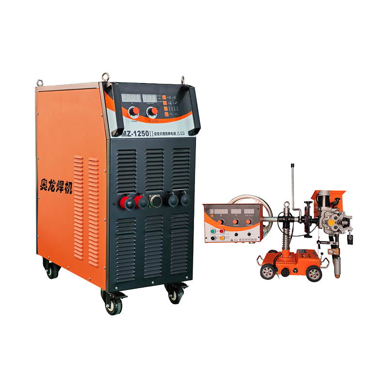
1、Two functions, submerged arc welding and manual welding. 2、High load...
See Details
1、High-power laser welding machine, suitable for heavy-duty industrial...
See Details
1. The welding machine communicates with the control pad, and all para...
See Details
1. The welding machine communicates with the control pad, and all para...
See DetailsRequest for a call today

Tel: 4000707018

E-mail: aolohj@163.com

Add: Factory Building No. 5, Phase II, Pioneer Park, Economic Development Zone, Taizhou City, Jiangsu Province, China.
Copyright 2023 Jiangsu Aolong Electric Technology Co., Ltd. All Rights Reserved.
 Privacy Policy Industrial Welding Machine Manufacturers


Contact Us